© Paul E. Bennett. 1994, 1998
® All rights reserved Paul E. Bennett 1994, 1998
No liability whatsoever is accepted by Paul E. Bennett
for any errors or omission in the presented material as published in
Forthwrite, the newsletter of the Forth Interest Group (UK) or on the
Forth Interest Group Websites.
by Paul E. Bennett
In the past two articles, we considered the input side. This article takes a look at some outputs and ways to control things. In this article we will cover simple relay based output.

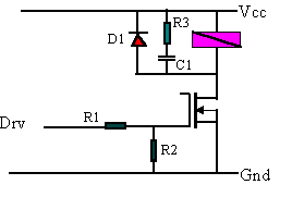
Figure 1 - Relay Drive
In Figure 1 the relay coil driver (A MOSFET but could be bipolar transistor) turns on when a voltage is applied to R1. While R1 should be a lowish value R2 needs to be a high, but included, to ensure a turn-off path for the transistor. The network D1, R3 and C1 is included to minimise the energy from back EMF destroying the transistor driver. In selecting driver transistors it is usual to ensure the maximum device ratings are at least 3 times greater than the demand of the load to ensure adequate margin of operation.
The output of Figure 1 is usually driven from a latch, set by software, to the state required of the output. A logical one representative of an energised output. The relay is a useful device for switching external circuits and provides a good degree of isolation. The contacts can be made available to the outside world as “volt-free” (meaning that they are to be considered just like individual switches) or could be linked to a power supply as a controlled supply distribution switch.
It is not enough to just set an output state and hope that it continues to follow your programmes desire. There are many reasons why an output could vary from the intent, including driver supply failure or component failure. It is therefore important to have a philosophy for controlling outputs.

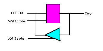
Figure 2 - Output Latch (with readback)
The latch shown in Figure 2 has a readback facility. The circuit is usually formed, in discrete logic components, with a 74xx373 D-type latch and a 74xx244 as the read-back buffer. To set or reset and check a bit the following code would suit (note that only one output port address is considered here).
HEX 8000 CONSTANT OUTPORT 8004 CONSTANT INPORT : SET-BIT (S bit-mask --- ) : RESET-BIT (S bit-mask -- ) : BIT-COMPARE (S --- bit-in-error ) |
When using a relay, it is very good practice to use a normally open and normally closed contact pair from the relay as feedback to the processor (via suitable inputs). The state of the relay contacts can then be compared to the state of the output latch as a cross-check that the real state of output is as expected. BIT-COMPARE works with a complementary state feedback from the relay contacts. Such cross checking becomes very important for high integrity control systems but is well worth considering for all systems requiring such control.
Further Levels of Abstraction
There may be good system reasons for control algorithms not to directly influence the setting and resetting of the output latch bits. A further level of abstraction can be achieved by creating an output bit array which is copied to the real output latches on-block. Such abstraction is useful when the output control algorithm is more complex than a simple on-off control.
If, instead of driving a relay, the output was driving an indicator which is required to have three states, ON, OFF and FLASHING the extra layer of abstraction can be very useful. The code below shows the changes that would be needed to implement the abstracted layer for output states.
VARIABLE OUTSTATE : SET-BIT (S bit-mask --- ) : RESET-BIT(S bit-mask -- ) : SET-FLASH(S bit-mask -- ) : RESET-FLASH(S bit-mask -- ) : COPY-OUTSTATE (S -- ) |
As can be seen in the above code adding to the level of abstraction does mean some extra complexity in the code.
Finally, for this article, a word of caution about controlling outputs. If you are planning to run machinery off of the controlled outputs (motors, actuators, solenoids etc) be sure to assess the risks associated with the action being performed. A system designer should always be aware of the risks of inadvertent activation of outputs.
Consideration of timing issues and analogue output methods.